can anyone help me get a pin out for this ford alarm ? i need to know what each wire does
If you are looking for the pinout of the 4-pin connector on the JS7Z-19A361-A unit, it is just CANBUS and power. This is taken from the GWM connection in the T-harness. Look at the GWM wiring for the truck, you will see the connections are just splices in the harness, FT4J-14B504-AA.
so i checked the gwm but still not what i wanted so that alarm has to have a way to be able to connect and external siren or to find out which cable is the trigger point or auxilary cable it has to wires which are cut
Ok, I’ll have to research that.
EDIT: The Ford alarm system sends the alert thru CANBUS to the BCM which controls the horn and lights.
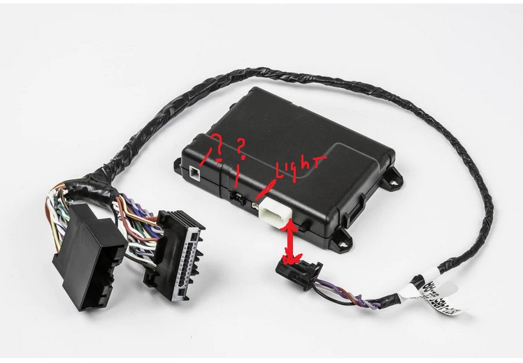
There are 2 wires that are not on the connector, they are loose for splicing? Like this…
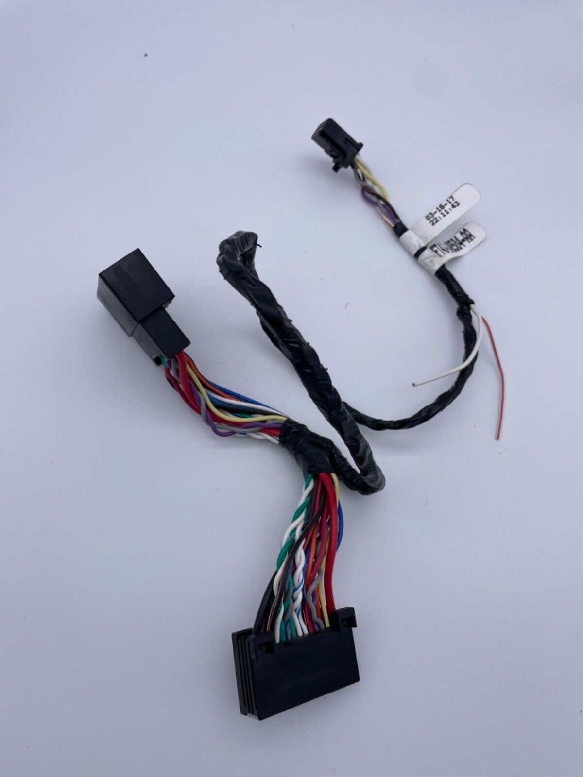
Those 2 wires are for the hood pin or latch kit, I believe. That feature is optional. There is no external horn feature for this unit.
I found this video which shows the installation…
Updated Ford Remote Start W/ Security System Install For Many Makes and Models KN1Z-19A361-A - YouTube
This thread has a lot of useful info:
Official Ford Lock-Unlock-Lock Remote Start - Ford F150 Forum - Community of Ford Truck Fans
ok so here goes my other question forscan has the option to enable a siren could that be for police units f150 ?
so those two wires they’re trigger wires? how could i test them do i have to enable them ?
I don’t know. Do you have the manual for the unit? I can’t seem to find this one.
did u receive the manual?