PINPOINT TEST T : THE COMPASS/NAVIGATION IS INOPERATIVE OR DOES NOT OPERATE CORRECTLY
Before performing this test, check for any applicable service articles: TSB, GSB, SSM or FSA. If a service article exists for this concern, discontinue this test and follow the service article instructions.
DTC Fault Trigger Conditions
-
APIM B119F:01 GPS Antenna: General Electrical Failure
Sets in continuous memory when the APIM detects a short to ground or short to voltage from the GPS antenna cable. -
APIM B119F:13 GPS Antenna: Circuit Open
Sets in continuous memory when the APIM detects an open from the GPS antenna cable.
Possible Sources
- Corrosion
- Network communication concern
- Obstructions in the GPS antenna line of sight to the satellite
- GPS antenna cable
- Roof mounted antenna
- ACM
- APIM
NOTE: Carrying out a Master Reset of the SYNC system prior to diagnostics may resolve some compass/navigation concerns.
T1 CHECK FOR ABS (ANTI-LOCK BRAKE SYSTEM) MODULE NETWORK COMMUNICATION
- Ignition ON.
- Using a diagnostic scan tool, clear the APIM Diagnostic Trouble Codes (DTCs).
- Ignition OFF.
- Ignition ON.
- Wait 30 seconds.
- Using a diagnostic scan tool, carry out the APIM self-test. (FORScan can perform this function.)
Is DTC U0121:00 present?
Yes GO to Pinpoint Test AD
No GO to T2
T2 CHECK THE GPS (GLOBAL POSITIONING SYSTEM) ANTENNA RECEPTION
- Access “APIM Diagnostics” using Bezel Diagnostics.
- Select “Location Information”.
NOTE: If the value reads less than 3 for “Number of Satellites” or “No GPS Fix” for “Fix Mode”, drive the vehicle to an outdoor location free from obstacles such as tall buildings and large trees. Monitor the “Number of Satellites” and “Fix Mode”.
Are 3 or more satellites displayed for “Number of Satellites” and is “3D fix obtained” displayed for “fix Mode”?
Yes GO to T3
No GO to T4
T3 CHECK COMPASS FOR CORRECT OPERATION
- Operate the vehicle and observe the compass heading.
Does the compass operate correctly?
Yes The system is operating correctly at this time. The concern may have been caused by obstructions in the antenna line of sight to the satellites for an extended period of time.
No GO to T13
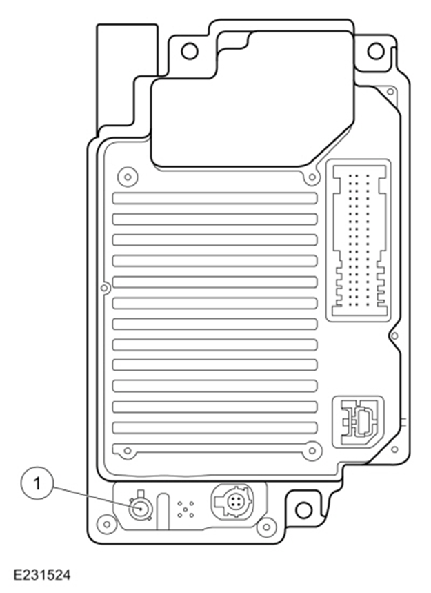
T4 CHECK FOR CORRECT APIM (SYNC MODULE) OUTPUT VOLTAGE AT THE GPS (GLOBAL POSITIONING SYSTEM) CABLE CONNECTION
- Ignition OFF.
- Disconnect GPS antenna cable from the APIM .
- Ignition ON.
- Using the female Flex Probe 300-08058 (0.5 mm x 0.5 mm) or equivalent, measure:
Positive Lead Measurement / Action Negative Lead
GPS cable core at the APIM (component side) Ground
Is the voltage between 4.7 and 5.8 volts?
Yes For vehicles not equipped with a satellite radio, GO to T9
For vehicles equipped with a satellite radio, GO to T5
No GO to T13
T5 CHECK FOR PREVIEW CHANNEL 1
- Operate the audio system in satellite radio mode.
- Select channel 1.
Does the satellite radio system receive channel 1 with normal sound quality?
Yes GO to T10
No GO to T6
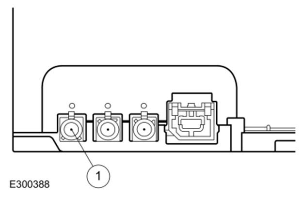
T6 CHECK FOR CORRECT ACM (AUDIO FRONT CONTROL MODULE) OUTPUT VOLTAGE TO THE SATELLITE RADIO ANTENNA CABLE
- Ignition OFF.
- Disconnect the satellite radio antenna cable at the ACM .
- Ignition ON.
- Using the female Flex Probe 300-08058 (0.5 mm x 0.5 mm) or equivalent, measure:
Satellite cable core (component side) Grd
Is the voltage between 4.7 and 5.8 volts?
Yes GO to T7
No GO to T12
T7 CHECK FOR VOLTAGE TO THE SATELLITE RADIO/GPS (GLOBAL POSITIONING SYSTEM) ANTENNA
- Ignition OFF.
- Connect the satellite radio antenna cable at the ACM .
- Disconnect the GPS/satellite radio antenna cable from the satellite radio antenna.
- Ignition ON.
- Using a multimeter or equivalent, measure:
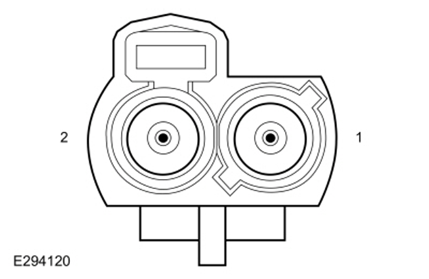
GPS/satellite radio antenna cable core at the antenna, cavity 1 Grd
Is the voltage between 4.7 and 5.8 volts?
Yes GO to T8
No IDENTIFY the cable with the open or short. INSTALL a new GPS/satellite radio cable for the one in question.
T8 ISOLATE THE SATELLITE RADIO/GPS (GLOBAL POSITIONING SYSTEM) ANTENNA SPLITTER CABLE
- Install a new satellite radio/GPS antenna splitter cable.
- Operate the vehicle and observe the compass heading.
Does the compass operate correctly?
Yes The repair is complete. The concern was caused by the original satellite radio/GPS antenna splitter cable.
No GO to T10
T9 CHECK FOR VOLTAGE TO THE GPS (GLOBAL POSITIONING SYSTEM) ANTENNA
- Ignition OFF.
- Disconnect the GPS antenna cable from the GPS antenna.
- Connect the GPS antenna cable to the APIM .
- Ignition ON.
- Using a multimeter or equivalent, measure:
GPS/satellite radio antenna cable core at the antenna, cavity 1 Grd
Is the voltage between 4.7 and 5.8 volts?
Yes GO to T10
No IDENTIFY the cable with the open or short. INSTALL a new GPS/satellite radio cable for the one in question.
T10 CHECK THE ANTENNA BASE AND MOUNTING SURFACE
- Remove the antenna.
- Inspect for corrosion on the antenna base and the vehicle mounting surface.
Is antenna base and mounting free of corrosion?
Yes GO to T11
No REPAIR any corrosion on the antenna base and/or vehicle mounting surface. INSTALL the antenna and make sure the correct torque value is used when tightening the fastener.
T11 CHECK THE ROOF MOUNTED ANTENNA
- Install a new roof mounted antenna.
- Test the system for normal operation.
Does the compass operate correctly?
Yes The repair is complete. The concern was caused by the roof mounted antenna.
No GO to T13
T13 CHECK FOR CORRECT APIM (SYNC MODULE) OPERATION
- Ignition OFF.
- Disconnect and inspect all the APIM and any related in-line connectors.
- Repair:
-
- corrosion (install new connectors or terminals - clean module pins)
-
- damaged or bent pins - install new terminals pins
-
- pushed-out pins - install new pins as necessary
- Reconnect the APIM and any related in-line connectors. Make sure they seat and latch correctly.
- Operate the system and determine if the concern is still present.
Is the concern still present?
Yes Check for any applicable service articles: TSB, GSB, SSM or FSA. If a service article exists for this concern, discontinue this test and follow the service article instructions.
No The system is operating correctly at this time. The concern may have been caused by module connections. Address the root cause of any connector or pin issues.