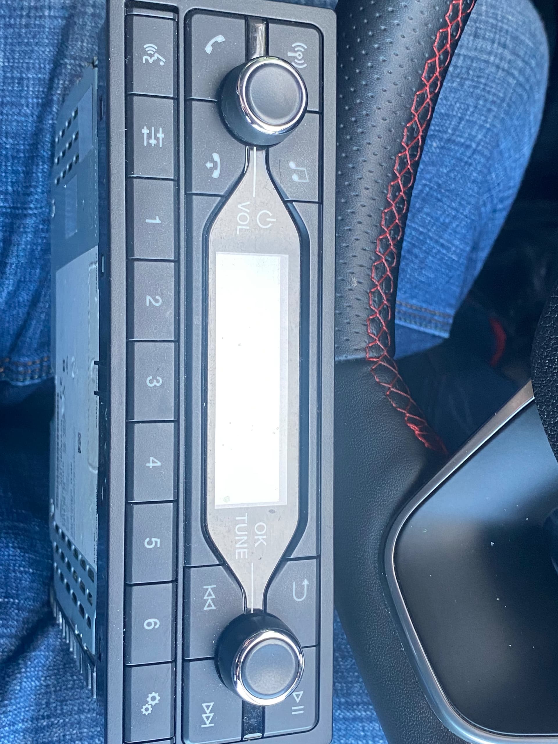
Hi I’ve been trying to retrofit sync 3 into a 2018 transit custom base which only had a 1 DIN very basic radio.
I have access to FDRS wiring diagram so have made my own wiring looms which I have installed.
All connections seem correct I have connected the high speed cam bus in line with the dc to dc converter and the low speed cam bus is the original wires at the factory audio plug.
I can see all the hardware in FORScan ACM APIM but can’t get FCDIM to switch on.
Just a black screen.
All buttons work volume etc and illuminate when the radio is switch on.
To me it sounds like it needs a wake up command possibly from the gate way module.
Any help would be much appreciated
Well have you made the STM32 based bench tester? Can you get the APIM / Screen (FCDIM) to turn on outside of the car?
If you have a blank screen it sounds like something else is going on.
Also I do not understand this: “I have connected the high speed cam bus in line with the dc to dc converter and the low speed cam bus is the original wires at the factory audio plug.” What low speed and high speed can bus are you talking about? and what dc-dc converter? The APIM takes +12vdc so you would not need to have a dc-dc stepdown, that is only used for the STM32 board which you would also not need if you are installing this in a newer ford vehicle.
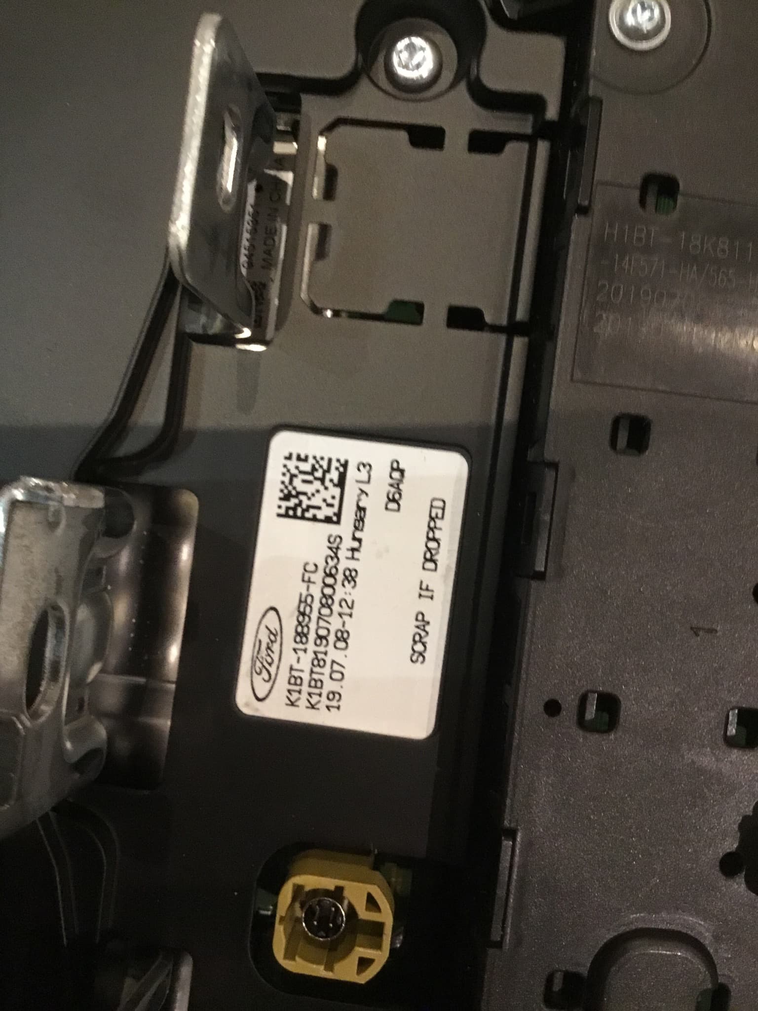
Do you have photos or a diagram of the harness you made?
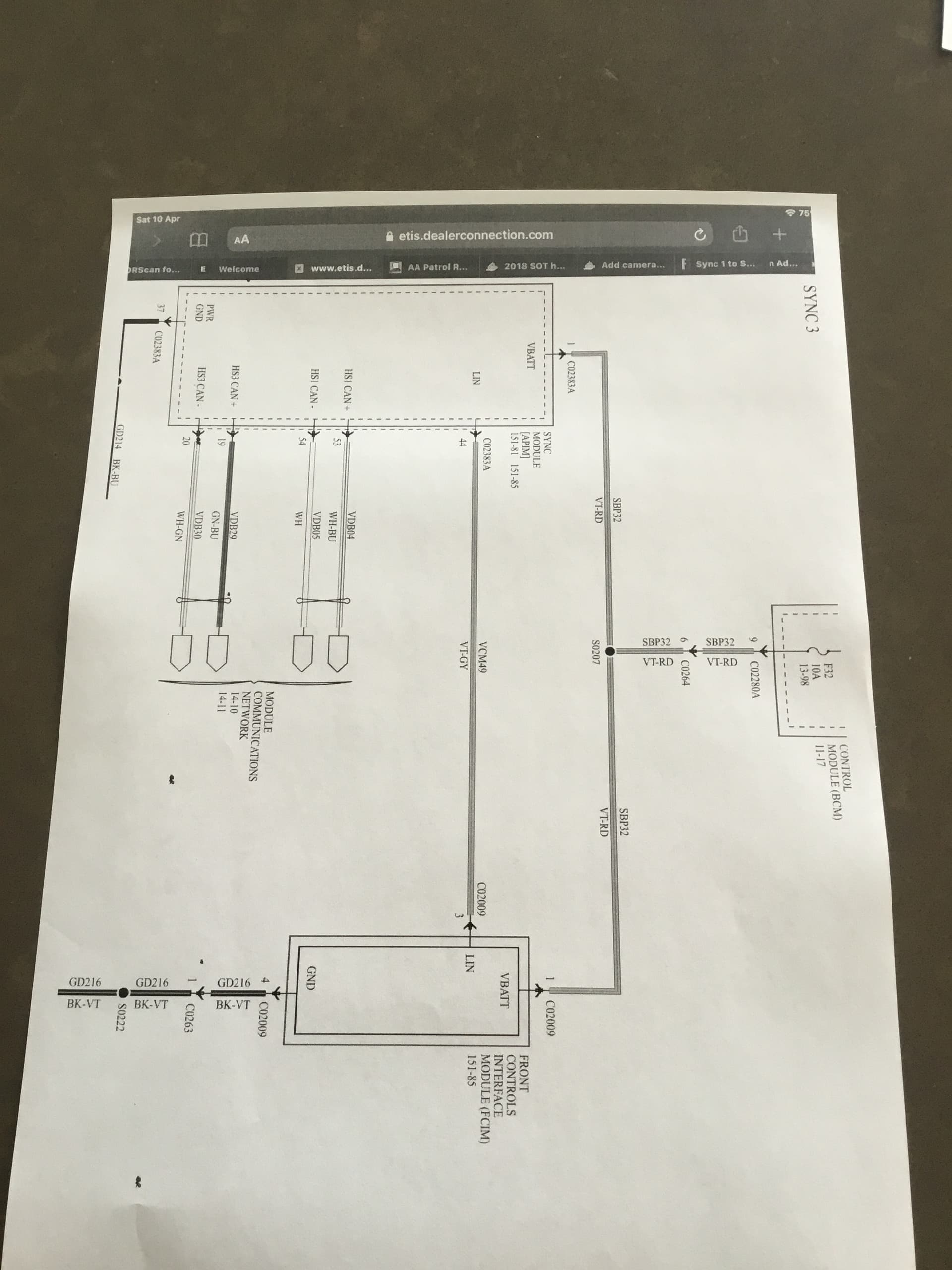
Sorry hard to explain basic the HS1 from pins 53 and 54 APIM white/blue and white I have connected to the HS1 cam bus line at the vehicle dc to dc converter and the HS3 from pin 19 and 20 green\blue and white\green at the vehicle factory audio plug.
Do you need to be connected to the HS1 and HS3 data line to make the FCDIM (display) work.
The FCDIM (display) works with a ACM out of transit connect fine with apple play and steering wheel control just no APIM (sat-nav) with that setup.
So, you spliced into the HS1-CAN at the DC Converter module.
HS3-CAN thru the factory plug.
I am not sure that the screen you are using from the Sync 1 setup will work. Maybe someone will chime in on this, but I remember people doing this swap also replaced the screens with the 6.5 inch model.
The screen the right one 8”
I have changed the the surround for a factory look.
The base model only had a Single din radio not even sync 1.
1 Like
That is what is was thinking. The FCDIM should be connected to the screen with the LVDS plug.
Does the screen and housing have another connector other than the LVDS 4 pin plug? Does your screen surround have audio controls?
So basically assuming my retrofit wiring between the APIM and the ACM are correct and all powers and earths are fine does the HS1 or HS2 cam bus lines control the FCIDM (display) to switch on. I assume they do as the FCIDM should switch off when the door is open etc.
so on a bench test setup I gather a gateway module or cam bus emulator is needed.
I think you need to bench test your screen and APIM combo outside the car to make sure they actually work, using my STM32 project.
There are are multiple things that could be wrong, but it would rule out faulty APIM configuration or hardware issues.
The screen it self needs only LVDS to power on / display an image.
Temporary I have fitted a ACM which has a LVDS output and both work perfectly.
So I know my screen and LVDS cable is working.
I have 2 APIM module one with nav one without both blank screen.
So it’s either my wiring which I have checked numerous times or gateway can bus…
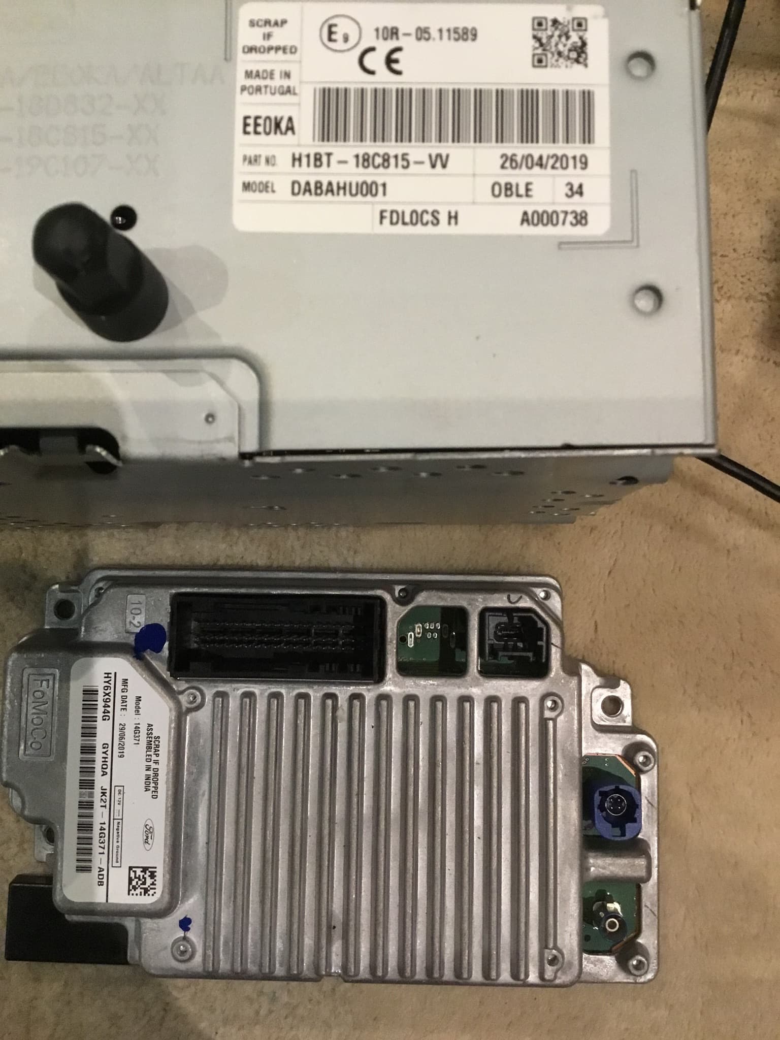
On the APIM in the picture above, you are connecting the Blue LVDS 4 pin connector to the screen from the APIM? What is the part numbers of the APIM’s and the screen? You may have a vdieo driver issue if you are using the screen in the pic above.
There is no HSx connection for your screen in this scenario.
I’m going to double check my wiring loom, I have been following the wiring diagram on FDRS for my VIN .
Has any got a wiring diagrams for the APIM I can check against the Ford one.
Thanks.
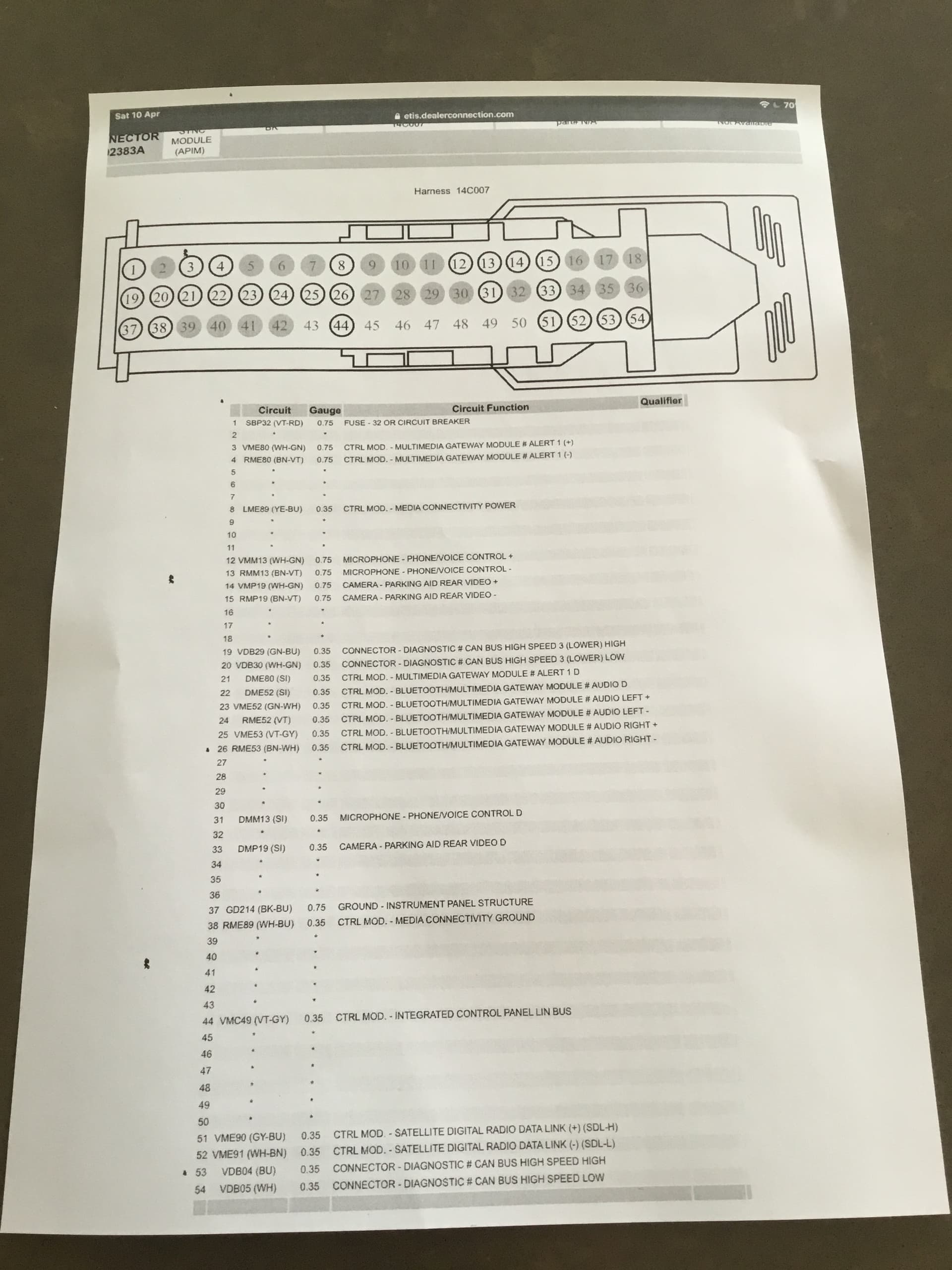
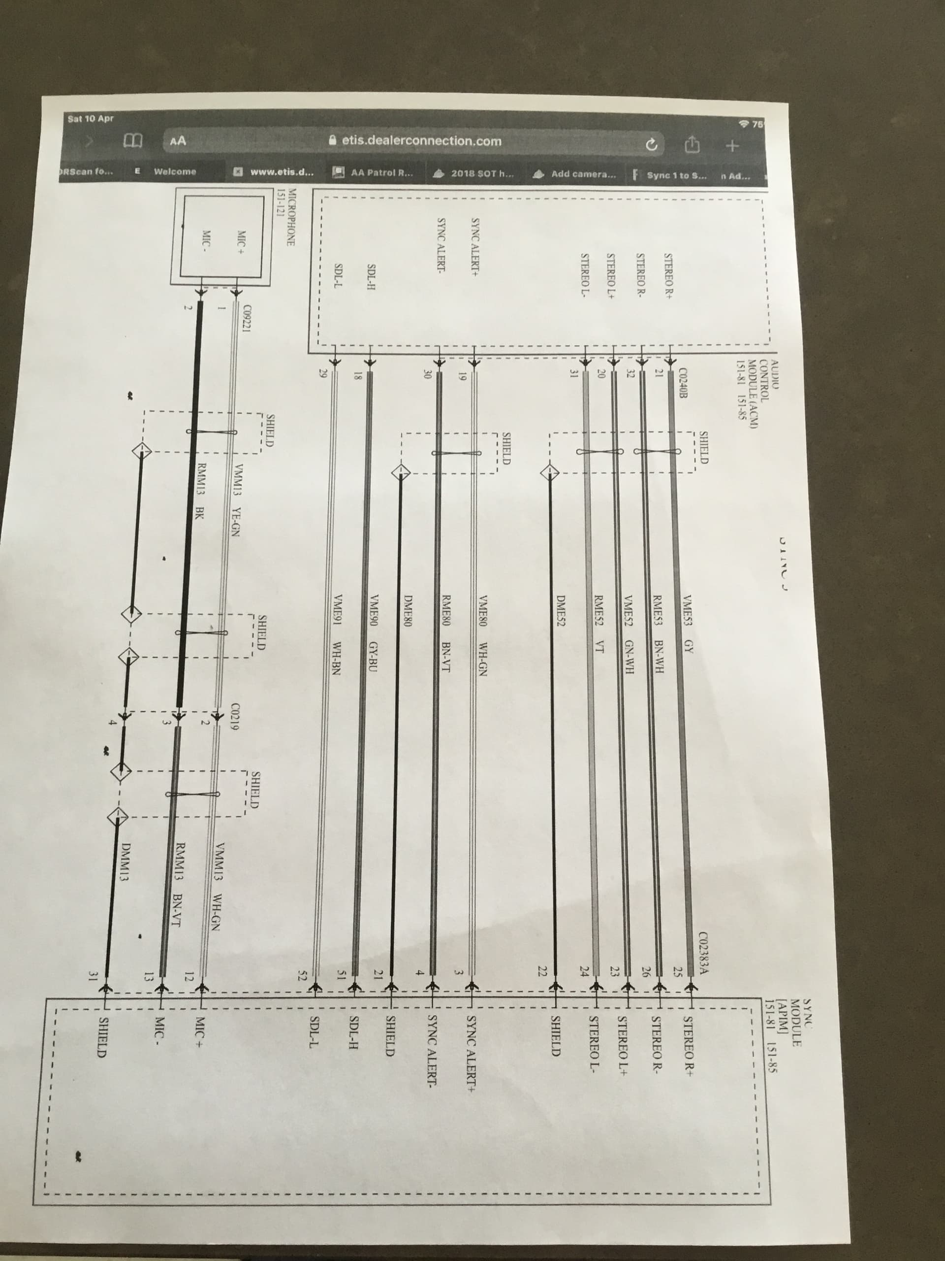
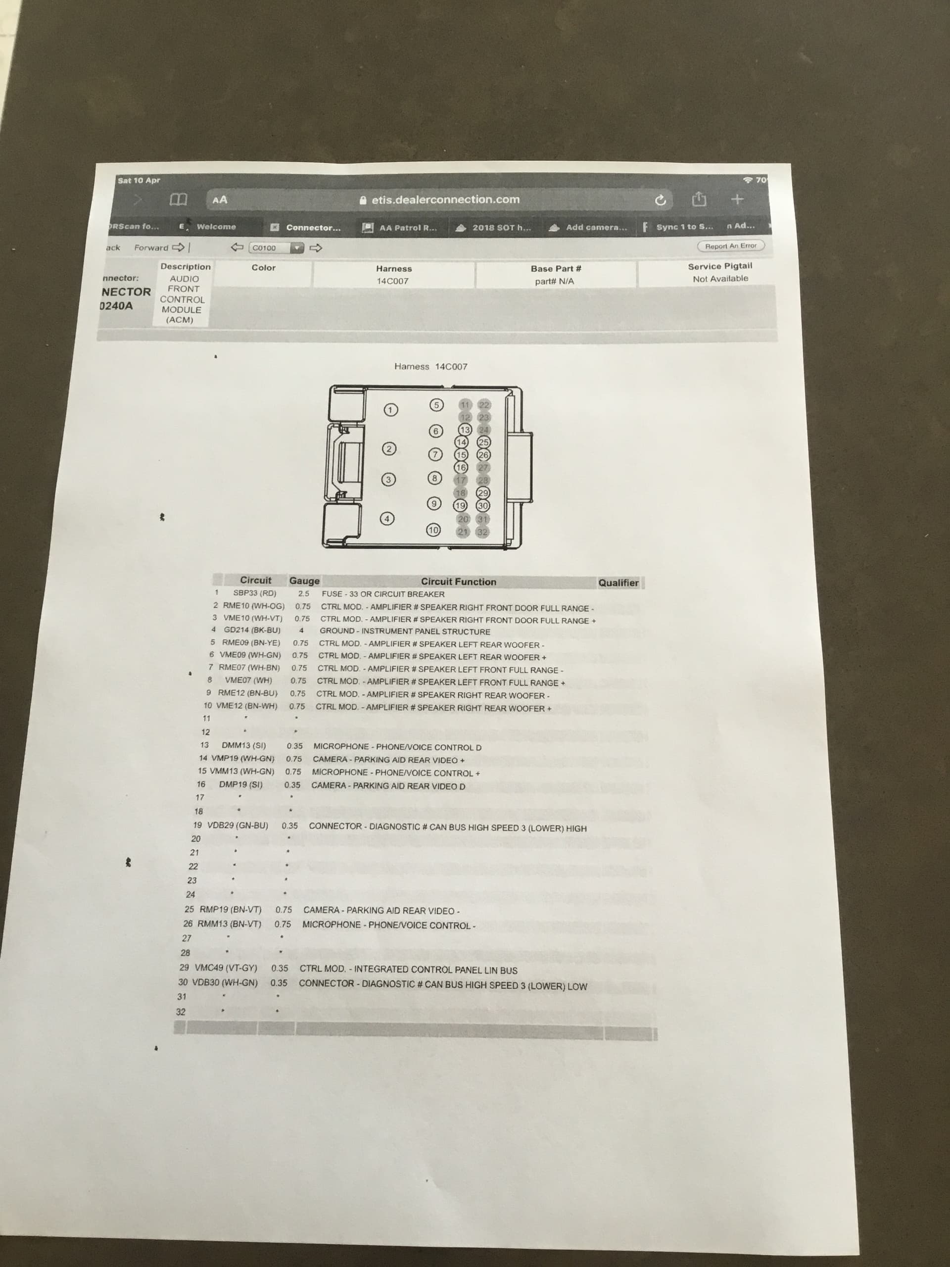
The wiring looks correct for the ACM.
This might help with the APIM, but it looks ok.
APIM Connector Versions.pdf (201.0 KB)
Make sure the LVDS and LIN-BUS are connected between the APIM and FCIM.
Check the APIM asbuilt for setting the LIN for the EFP at:
7D0-02-02 xxxx xxx* xx–
ICP (EFP) Network, ECALL, Online Traffic for SA/China, Brazil Frequency Supported by Radio
If this is a ‘0’, change it to ‘8’.
I moved this to it’s own thread…
Update regarding this problem of a blank screen when retrofit .
The ACM , FCIM and APIM module were all from different vehicle recheck the wiring loom all fine.
Download 3.4 update to a usb plug it in screen was still blank for about 60 sec then got a white mustang upload screen which is the first time I’ve seen that working with these module. Download took about 50 mins and now every is working perfectly so many thanks for all your help.
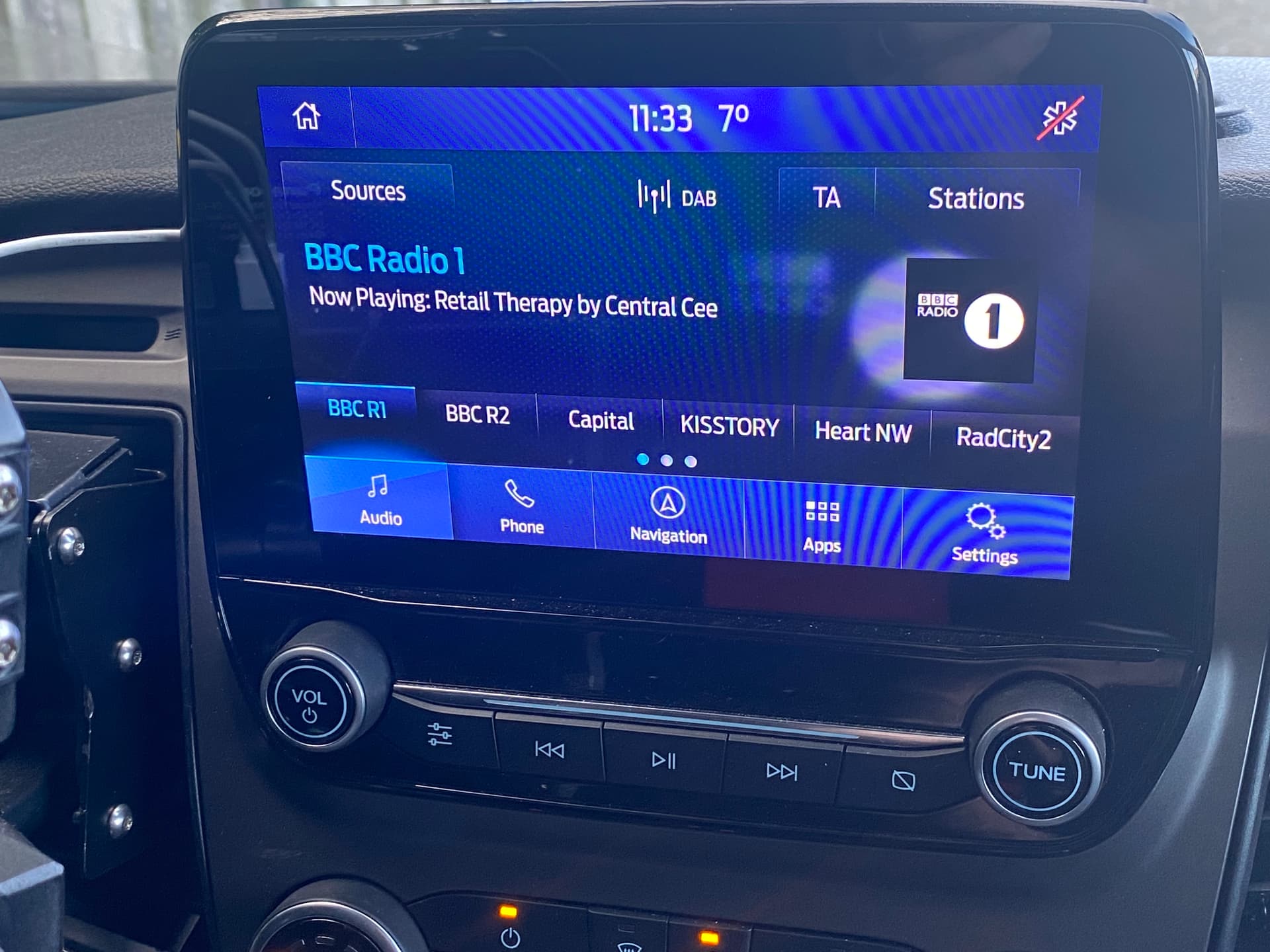
Gone from single Din FM only pieces of rubbish to this nav and dab.
5 Likes
If you could, would you share your APIM, ACM, and FCIM asbuilts here to help others in the future?
Good work, glad you got it working. Definitely better than the old unit. Enjoy.
1 Like
This topic was automatically closed 5 days after the last reply. New replies are no longer allowed.